The topic of high availability Internet connectivity is a constant conversation I have with my customers and teammates and I finally thought it best to sit down and draw the various options. These options assume you have two FortiGates in HA (I don’t get into Active-Passive vs. Active-Active for HA, but believe both HA types should work) and two Internet providers. Let’s get started!
Two Hand-Offs Per ISP
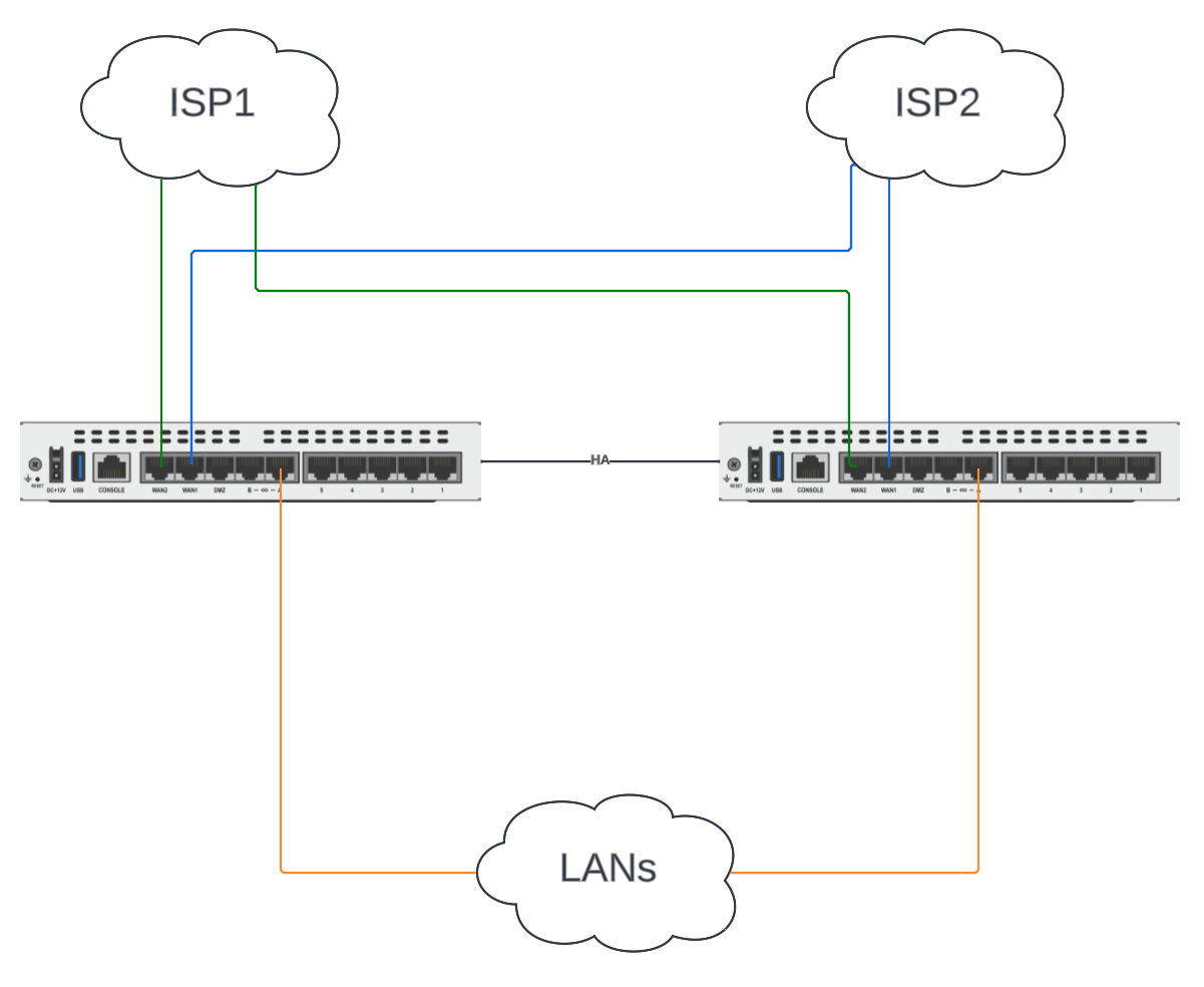
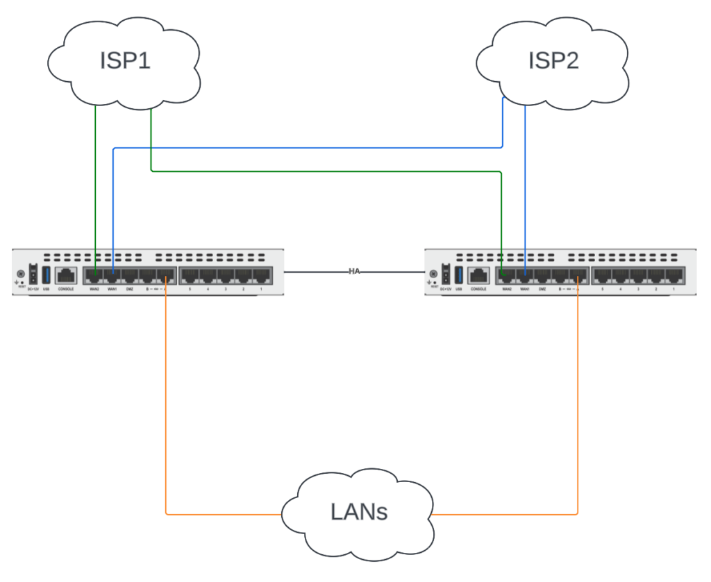
This is our dream scenario, one in which each of our ISPs hand us two cables from their provider-edge equipment. If only this were reality! But when we’re so lucky, we connect each Internet hand-off to the same interface on each FortiGate. In the example below, ISP1 (the green line) plugs into wan2 on each FortiGate and ISP2 (the blue line) plugs into wan1 on each FortiGate. All we have to do is configure HA and the wan interfaces on our Primary FortiGate and the rest is seamless.
Pros
- If a FortiGate fails, we have that Internet connection on the surviving FortiGate and can still use SD-WAN to utilize both circuits.
- Simple configuration on FortiGates: just assign IPs from each ISP on each wan interface, then HA syncs it to the Standby or other Active unit.
- Possibly lower cost because no additional hardware is necessary for you.
Cons
- If an ISP has a provider-edge equipment failure, it would make that Internet hand-off unavailable on each FortiGate. (OK, but that’s why we’d use SD-WAN to detect and redirect traffic appropriately)
- Requires provider-edge equipment that can accommodate multiple cable hand-offs, which is not often the case.
Physical Switches
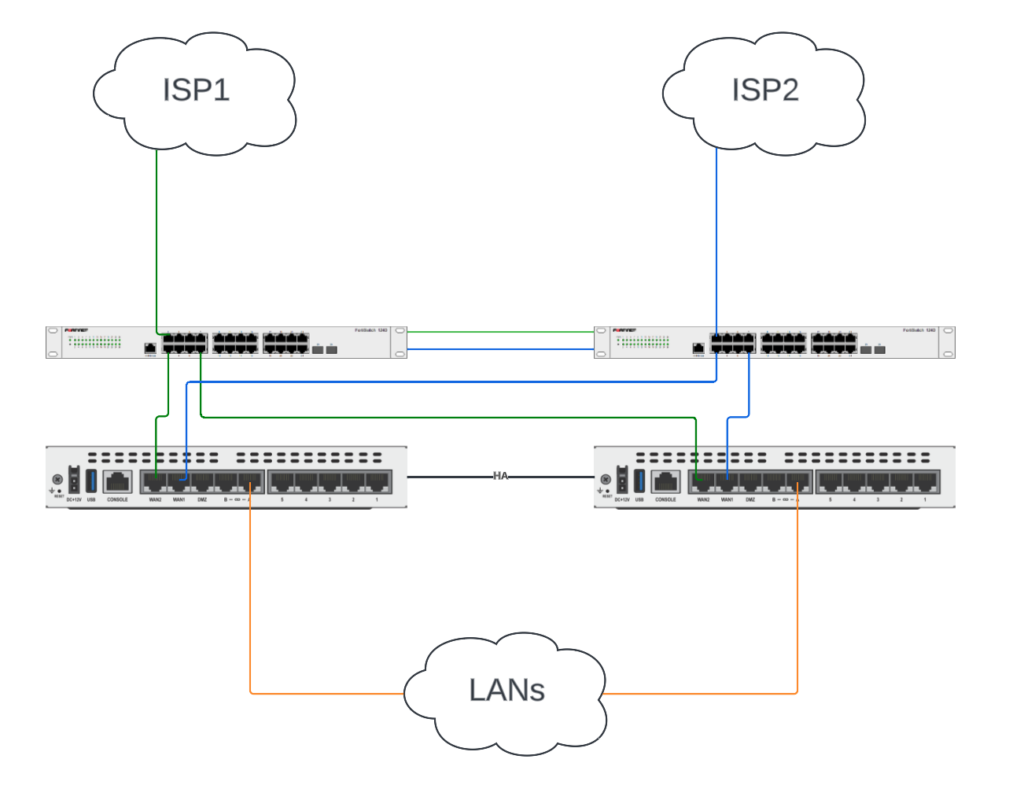
In this scenario, we only have one Internet hand-off from each ISP and need to split it out to each FortiGate. This requires a physical switch (or two is better) between the Internet provider-edge equipment and the FortiGates. We need to do everything we can to prevent these physical switches from being a single point of failure: redundant switches, redundant power on each switch and redundant connectivity between switches.
In the diagram below, I have two standalone FortiSwitches north of the FortiGates. We create a different VLAN for each Internet connection and share that across a 802.1q LACP port-channel ISL between the FortiSwitches.
Pros
- If a FortiGate fails, we have that Internet connection on the surviving FortiGate and can still use SD-WAN to utilize both circuits.
- Simple configuration on FortiGates: just assign IPs from each ISP on each wan interface, then HA syncs it to the Standby or other Active unit.
- The loss of a switch won’t cause a complete outage, it will just cause an outage for the one ISP.
Cons
- Added cost of two physical switches.
- Additional hardware to configure, maintain and support.
The added cost and maintenance is one of those trade-offs for the added redundancy. It won’t fit every build/site, but is a great option where needed.
FortiGate Hardware Switch
So far you’re thinking, these designs are agnostic to FortiGates and you’re right! They apply to any model router or firewall. But this next option is unique to FortiGate and it is utilizing a hardware switch to share the WAN VLANs between the FortiGates. It’s also the hardest to wrap your head around at first… or at least it was for me. But by the end of this section it’ll make perfect sense.
First off, let’s show how the two FortiGates are cabled:
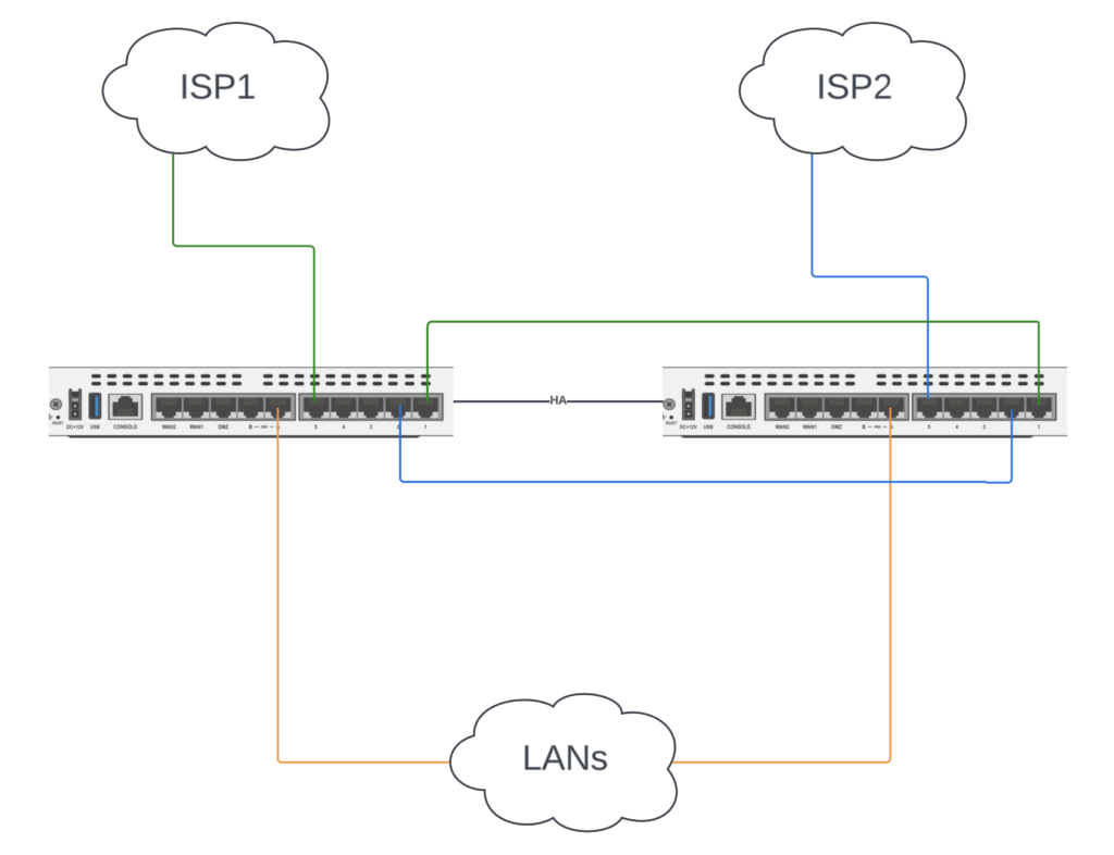
The unique aspect of this design is that we’re connecting the various internal interfaces on each FortiGate. Rather than connect wan1 or wan2 to each ISP, we’re connecting it to an internal interface so we can utilize it in a hardware switch. The number of Internet connections = the number of ports you’ll use on each FortiGate. We have 2 ISPs so we cross-connect 2 cables between the FortiGates.
A hardware switch is a virtual switch interface that groups different ports together so that the FortiGate can use the group as a single interface. Supported FortiGate models have a default hardware switch called either internal or lan. The hardware switch is supported by the chipset at the hardware level.
https://docs2.fortinet.com/document/fortigate/7.2.5/administration-guide/100999/hardware-switch
In our example below, on the left FortiGate we group the green lines internal5 (uplink to ISP1) and internal1 (cross-connect to other FortiGate) into Hardware Switch HW_SW1 and assign HW_SW1 the IP address x.x.x.x. And likewise on the right FortiGate, we group the blue lines internal5 (uplink to ISP2) and internal2 (cross-connect to other FortiGate) into Hardware Switch HW_SW2 and assign HW_SW2 the IP address y.y.y.y.
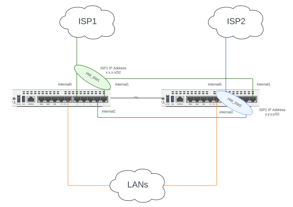
By grouping the two internal interfaces into Hardware Switches, we can use both ISPs on both FortiGates with only 1 network hand-off from each ISP. When the left FortiGate is the Primary, we reach ISP1 via internal5 on HW_SW1 (green line) and we reach ISP2 via the cross-connect internal2 on HW_SW2 (blue line). When the right FortiGate is the Primary, we reach ISP1 via the cross-connect internal1 on HW_SW1 (green line) and we reach ISP2 via internal5 on HW_SW2 (blue line). The full configuration steps can be found on this FortiDocs page: https://docs.fortinet.com/document/fortigate/7.0.1/administration-guide/931221/configuring-sd-wan-in-an-ha-cluster-using-internal-hardware-switches.
What does this mean for failures though? Well, it’s not as good as our first two options (two hand-offs or physical switches). If one of the FortiGates dies, HA will failover to the surviving FortiGate but we’ll lose the ISP connected into it relying on the surviving FortiGate and ISP.
Pros
- Can utilize both ISPs on either FortiGate, even with one network hand-off.
Cons
- Failure of a FortiGate results in failure of the connection to that ISP.
- Consumes more interfaces on each FortiGate (1 per ISP).
- Configuration complexity (the one time you set it up).
I need to shout out to my awesome teammates who showed me this design and then explained it to me (more than once) when I first joined Fortinet. Thanks Derek Ellis and Mike Butterfield!
FortiGate Bypass
This is the “honorable mention” option where it doesn’t solve a lot of redundancy problems, but it does solve one. Should your FortiGate lose power or die, you can leverage certain FortiGate Bypass models to maintain connectivity to the ISP via a redundant interface. Our FortiGate 80F/81F comes in this Bypass model and it pairs WAN1 with internal1. In the event of an appliance failure, it bypasses any switch or security in the FortiGate and essentially connects WAN1 with internal1. This could be useful when you need a fail-open scenario. But with the caveat that if the FortiGate was providing NAT or routing then of course you wouldn’t see those benefits in the event that it dies. But the functionality is there should you need a fail-open solution. FortiDocs has a great write-up on the ASIC connectivity to achieve this as well as more details: https://docs.fortinet.com/document/fortigate/7.4.0/hardware-acceleration/300792/fortigate-80f-81f-and-80f-bypass-fast-path-architecture.
Conclusion
I hope this post helps you design redundant Internet connections with redundant FortiGates! It’s one of those topics that dusting the cobwebs off the different designs made this post necessary so I can go back and read it myself. Thanks for reading and please share your thoughts and questions in the comments below.
Andrew